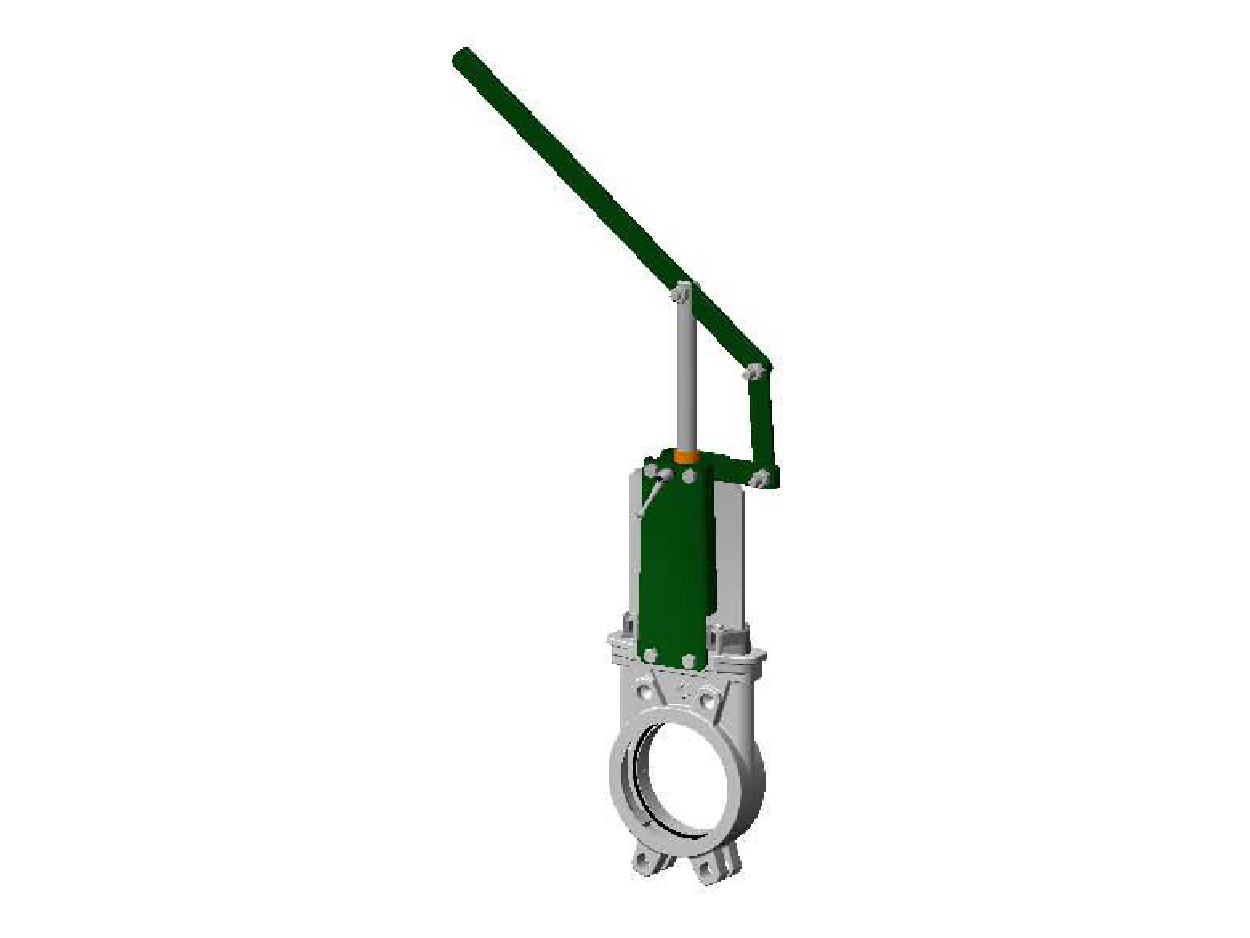
Knife Gate Valve With Lever 6400
APPLICATION
General use : Pulp production, water, water treatment, waste water, chemical industry (powdery or crystallizing products), wine-producing, pulverized products (cement work, pneumatic transport, stocking).
GENERAL CHARACTERISTICS
Function ON/OFF or regulation.
Wafer threaded mounting ISO PN10.
Unidirectional tightness, direction indication thanks to the arrow on the body. Small retention zone : the gate is guided in the body and has little clearance. Gland assembly : packing and O-ring (same material as seat joint) to assure the elasticity and decrease the operating force.
Small head loss.
Possibility to regulate thick fluids with the adaptation of a diaphragm ring .
WORKING CONDITIONS
Maximum working pressure : DN 50-250 : 10 bar
DN 300 : 7 bar
Maxi temperature : -10°C / +130°C (standard tightness)
STANDARDS
Manufacture according to the requirements of the European directive 97/23/CE «Equipments under pressure» : modulate H.
On request : Product in accordance to european directive
“Potentialy explosive atmospheres” N°94/9/EC : ATEX II 2 GD c and ATEX II 3 GD c. Test procedures are established according to standard EN 12266-1, DIN 3230,
BS 5154 and ISO 5208
Connections according to standard EN 1092-2 and DIN 2501 : ISO PN10.
TECHNICAL INFORMATION
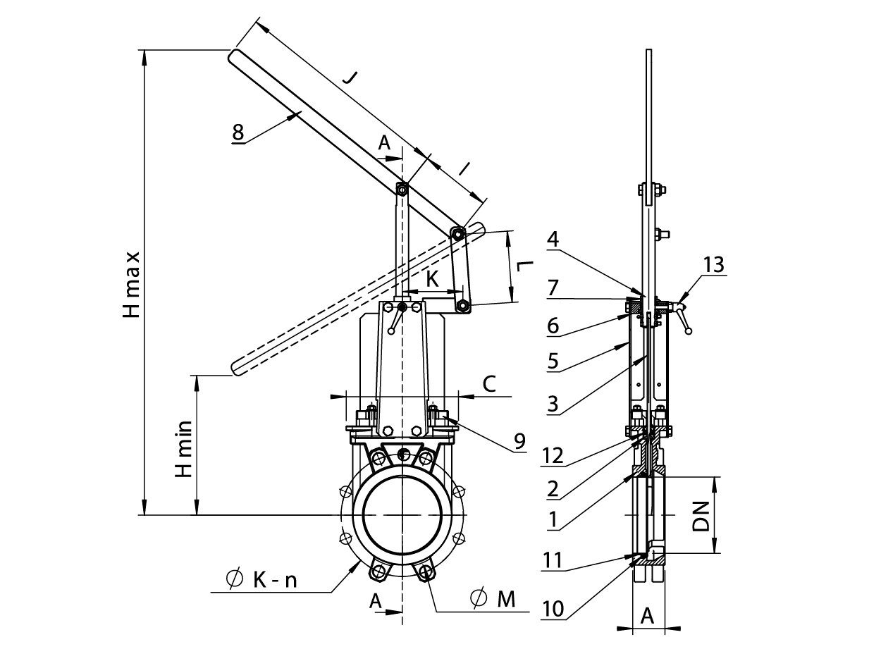
| DIMENSIONS | * Pre-shaped parts up to DN 300.**Missing parts on metal / metal tightness. | ||||||||||||||
| mm | DNinch | A | B | C | D | Ø V | H | Ø K | n | Ø M | Weight(kg) | D | |||
| 50 | 2″ | 40 | 283 | 124 | 83 | 200 | 348 | 125 | 4 | 4 x M16 | 7,5 | ||||
| 65 | 2″1/2 | 40 | 308 | 139 | 83 | 200 | 388 | 145 | 4 | 4 x M16 | 9,0 | M | 15 | ||
| 80 | 3″ | 50 | 333 | 154 | 83 | 200 | 413 | 160 | 8 | 4 x M16 | 10,0 | A | A | 1 | |
| 100 | 4″ | 50 | 378 | 174 | 83 | 200 | 488 | 180 | 8 | 4 x M16 | 11,5 | K – n | |||
| 125 | 5″ | 50 | 423 | 189 | 93 | 250 | 564 | 210 | 8 | 4 x M16 | 15,5 | ||||
| 150 | 6″ | 60 | 474 | 220 | 93 | 250 | 635 | 240 | 8 | 4 x M20 | 18,5 | ||||
| 200 | 8″ | 60 | 5 93 | 2 75 | 10 8 | 3 10 | 809 | 2 95 | 8 | 4 x M2 0 | 35,0 | ||||
| 250 | 10″ | 70 | 6 85 | 3 26 | 10 8 | 3 10 | 946 | 3 50 | 12 | 8 x M2 0 | 47,0 | ||||
| 300 | 12″ | 70 | 792 | 380 | 108 | 310 | 1118 | 400 | 12 | 8 x M20 | 61,0 | ||||
| 350 | 14″ | 96 | 900 | 438 | 290 | 500 | 1282 | 460 | 16 | 10 x M 20 | 117 | ||||
| 400 | 16″ | 100 | 978 | 494 | 290 | 500 | 1441 | 515 | 16 | 10 x M 24 | 151 | ||||
| 450 | 18″ | 106 | 1105 | 547 | 290 | 500 | 1587 | 565 | 20 | 14 x M 24 | 187 | ||||
| 500 | 20″ | 110 | 1215 | 613 | 290 | 500 | 1809 | 620 | 20 | 14 x M 24 | 205 | ||||
| 600 | 24″ | 110 | 1418 | 716 | 290 | 500 | 2060 | 725 | 20 | 14 x M 27 | 292 | ||||

